Open-Hole Tension of Carbon/Epoxy Laminates: Lay-up and Hole Size Effects
Key result: a $6\,\mathrm{mm}$ hole concentrates the stress by $K_T = 4.38$ in a $0°$-dominated carbon/epoxy laminate, $3.10$ in a quasi-isotropic one and $2.62$ in a $\pm 45°$-dominated one. The finite element values are within $1.1\%$ of Lekhnitskii's solution with Tan's finite-width correction. Without a hole, the $0°$-dominated laminate is $1.83$ times stronger than the quasi-isotropic one. With the hole, it is $1.30$ times stronger if the peak stress at the hole edge sets the strength, and $1.92$ times with the point stress criterion of Whitney and Nuismer. The two methods predict $23$ to $38\%$ and $53$ to $58\%$ of the unnotched strength: for this hole, the choice of method changes the allowable by a factor of up to $2.6$.
SUMMARY
Three carbon/epoxy laminates of 16 plies (one $0°$-dominated, one quasi-isotropic, one $\pm 45°$-dominated) were analysed in open-hole tension, the configuration of the ASTM D5766 test [ref. 1], in the finite element analysis (FEA) software Code_aster [ref. 2]. Each plate was modelled with layered shell elements (DKT, one layer per ply), with hole diameters of $3$ and $6\,\mathrm{mm}$ in specimens $6$ hole diameters wide, and in a plate $20$ hole diameters wide that stands in for an infinite plate. The ply stresses were checked against failure by the Tsai-Wu criterion (first-ply failure), the maximum fibre stress (fibre failure) and Hashin's matrix criterion.
The model was verified against the theory at every step. The laminate stiffness and the ply stresses far from the hole match classical lamination theory (CLT) within $1\%$. On the wide plate, the stress around the hole edge matches Lekhnitskii's exact solution for an infinite orthotropic plate within $0.34\%$ of the peak, and the stress concentration factors within $0.2\%$. On the specimens, they are within $1.1\%$ of Lekhnitskii's values with Tan's finite-width correction. The Whitney-Nuismer strengths computed from the FEA stress profiles are within $1.8\%$ of the closed-form predictions.
The strengths depend strongly on the method used to predict them. A check of the peak stress at the hole edge gives a strength independent of the hole size and penalises the $0°$-dominated laminate most, because its stress concentration is highest. The point stress and average stress criteria measure the stress at a characteristic distance from the hole. They predict that a $3\,\mathrm{mm}$ hole is $19$ to $30\%$ less damaging than a $6\,\mathrm{mm}$ one, and they keep most of the advantage of the $0°$-dominated laminate. Matrix cracking starts at the hole edge at $17$ to $30\%$ of the fibre failure load predicted by the point stress criterion.
INTRODUCTION
Every composite structure has holes: for fasteners, for access, for wiring and drains. A hole concentrates the stress at its edge and is often what sizes a laminate, so the open-hole tension (OHT) strength is one of the standard design allowables of aerospace composite structures, measured on coupons by ASTM D5766 [ref. 1].
In a metal, the stress concentration of a circular hole is about $3$ whatever the material, and the material yields locally before it fails. In a laminate, the stress concentration depends on the lay-up, from about $2.5$ to more than $6$, and the material does not yield: the plies crack and the fibres break. Two questions follow for the designer. First, how much does a hole cost each candidate lay-up? Second, since a laminate with a hole is almost always stronger than the peak stress at the hole edge suggests, how should the strength be predicted?
This study answers both on three typical lay-ups of the same carbon/epoxy ply. It first verifies the finite element model against the classical solutions: classical lamination theory for the laminate stiffness and the ply stresses, Lekhnitskii's solution for the stress around a hole in an orthotropic plate [ref. 3] and Tan's finite-width correction [ref. 4]. It then predicts the strength of each lay-up with a hole by two methods: the peak stress at the hole edge, and the point and average stress criteria of Whitney and Nuismer [ref. 5].
METHODOLOGY
The plates are modelled with layered shell elements. The mechanical behaviour is assumed to be linear and elastic, respecting the small strain hypothesis.
Figure 1 represents the general setup of the problem. The plate ($x$ along the load, $y$ across the width) is $W = 6D$ wide, with a central hole of diameter $D = 3$ or $6\,\mathrm{mm}$, as in ASTM D5766. It is $6W$ long, so the hole is $3W$ away from each end. One end rests on rollers ($u_x = 0$, with $u_y = 0$ at one node to remove the last rigid-body motion), so the plate can contract freely across its width. A uniform traction is applied to the other end, of resultant $\sigma_\infty W h$, with $\sigma_\infty = 100\,\mathrm{MPa}$ the gross stress and $h = 2\,\mathrm{mm}$ the thickness. The laminates are symmetric and the loads in-plane, so the plate does not bend: the out-of-plane displacement and rotations are fixed to zero at every node. The model is linear, so every result is proportional to $\sigma_\infty$, and the strengths below are obtained by scaling it.
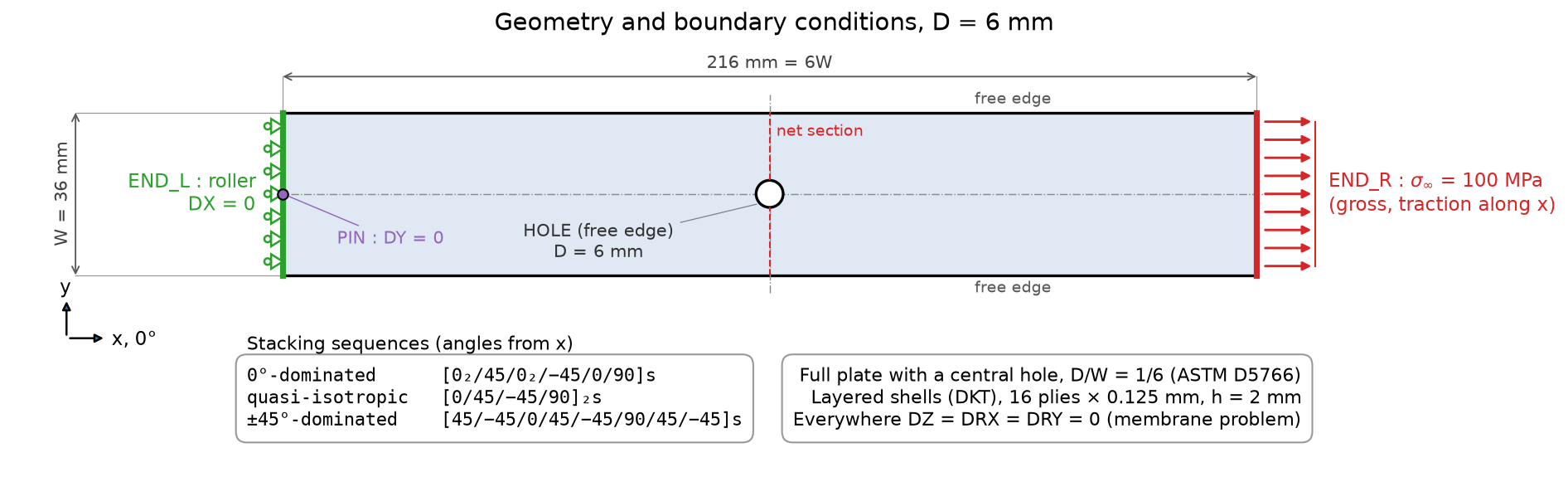
FIGURE 1. Geometry and boundary conditions, with the names of the groups of the model ($D = 6\,\mathrm{mm}$ shown). The net section is the line $x = 0$ from the hole to the free edge.
Material and lay-ups
The ply is an intermediate-modulus carbon/epoxy, with typical properties of the IM7/8552 class, and a thickness of $0.125\,\mathrm{mm}$:
| Property | Value |
|---|---|
| Moduli $E_1$, $E_2$, $G_{12}$ ($\mathrm{GPa}$) | $171.42$, $9.08$, $5.29$ |
| Poisson's ratio $\nu_{12}$ | $0.32$ |
| Tensile, compressive strengths along the fibres $X_T$, $X_C$ ($\mathrm{MPa}$) | $2326.2$, $1200.1$ |
| Tensile, compressive transverse strengths $Y_T$, $Y_C$ ($\mathrm{MPa}$) | $62.3$, $199.8$ |
| In-plane shear strength $S$ ($\mathrm{MPa}$) | $92.3$ |
The three laminates have 16 plies, $2\,\mathrm{mm}$ thick, and are symmetric and balanced. The angles are measured from the load axis $x$:
- $0°$-dominated $[0_2/45/0_2/{-45}/0/90]_s$: $62.5\%$ of $0°$ plies, $25\%$ of $\pm 45°$, $12.5\%$ of $90°$, a lay-up for a load path known in advance.
- Quasi-isotropic $[0/45/{-45}/90]_{2s}$: $25/50/25\%$, the same stiffness in every in-plane direction.
- $\pm 45°$-dominated $[45/{-45}/0/45/{-45}/90/45/{-45}]_s$: $12.5/75/12.5\%$, a lay-up for shear-loaded skins.
Classical lamination theory
Each ply is orthotropic, with a reduced stiffness $\mathbf{Q}$ in its own axes. Rotated to the laminate axes, it becomes $\bar{\mathbf{Q}}(\theta)$, and the in-plane stiffness of the laminate is the sum over the plies,
$$ \begin{equation} \mathbf{A} = \sum_k \bar{\mathbf{Q}}(\theta_k)\, t_k, \qquad \begin{pmatrix} N_x \\ N_y \\ N_{xy} \end{pmatrix} = \mathbf{A} \begin{pmatrix} \varepsilon_x \\ \varepsilon_y \\ \gamma_{xy} \end{pmatrix}, \end{equation} $$
where $N$ are the in-plane forces per unit width. The laminates are symmetric, so in-plane forces do not bend them. The strains are the same in every ply, and each ply's stresses are $\mathbf{Q}$ times the strains rotated to its axes. The effective moduli of the laminates, from $\mathbf{A}^{-1}$, are:
| Lay-up | $E_x$ ($\mathrm{GPa}$) | $E_y$ ($\mathrm{GPa}$) | $G_{xy}$ ($\mathrm{GPa}$) | $\nu_{xy}$ |
|---|---|---|---|---|
| $0°$-dominated | $117.97$ | $38.98$ | $14.95$ | $0.312$ |
| Quasi-isotropic | $64.51$ | $64.51$ | $24.60$ | $0.311$ |
| $\pm 45°$-dominated | $45.32$ | $45.32$ | $34.26$ | $0.516$ |
Stress concentration: Lekhnitskii and Tan
For a circular hole in an infinite orthotropic plate loaded along a principal axis $x$, Lekhnitskii [ref. 3] gives the stress along the edge of the hole, tangent to it, at the angle $\theta$ from the load axis:
$$ \begin{equation} \frac{\sigma_{\theta\theta}}{\sigma_\infty} = \frac{E_\theta}{E_x} \left[ -k \cos^2\theta + (1 + n) \sin^2\theta \right], \qquad k = \sqrt{\frac{E_x}{E_y}}, \qquad n = \sqrt{2 (k - \nu_{xy}) + \frac{E_x}{G_{xy}}}, \end{equation} $$
where $E_\theta$ is the laminate modulus along the tangent to the hole. At $\theta = 90°$, on the net section, the tangent is along $x$ and the stress concentration factor of the infinite plate is
$$ \begin{equation} K_T^\infty = 1 + \sqrt{2 \left( \sqrt{\frac{E_x}{E_y}} - \nu_{xy} \right) + \frac{E_x}{G_{xy}}} = 4.278,\; 3.000,\; 2.514 \end{equation} $$
for the three lay-ups. It is $3$ for the quasi-isotropic laminate, as for an isotropic plate, and it rises with the share of $0°$ plies: these make the plate stiff along the load and soft in shear, and the load then flows around the hole through a narrow band at its edge.
For a plate of finite width, Tan [ref. 4] gives $K_T / K_T^\infty$ as a function of $D/W$ and $K_T^\infty$, on the gross stress. At $D/W = 1/6$ it is $1.0316$, so $K_T = 4.414$, $3.094$ and $2.593$; at $D/W = 1/20$, it is $1.0026$.
Failure criteria and notched strength
Each ply is checked with three criteria, in its own axes ($\sigma_1$ along the fibres, $\sigma_2$ across, $\tau_{12}$ in shear):
- Tsai-Wu [ref. 6], a single quadratic criterion with $F_{12} = -\tfrac{1}{2}\sqrt{F_{11} F_{22}}$, for the first ply failure (FPF), in practice the onset of matrix cracking.
- Maximum fibre stress: $\sigma_1 = X_T$ or $-X_C$, for fibre failure. Hashin's fibre mode adds $(\tau_{12}/S)^2$ to $(\sigma_1/X_T)^2$, which makes the $\pm 45°$ plies "fail in the fibres" under matrix shear. Shear is left to the matrix criteria here.
- Hashin, matrix modes [ref. 7]: $(\sigma_2 / Y_T)^2 + (\tau_{12}/S)^2 = 1$ in tension, $(\sigma_2 / Y_C)^2 + (\tau_{12}/S)^2 = 1$ in compression (with a transverse shear strength $Y_C/2$).
The unnotched strength $\sigma_0$ of each laminate is the gross stress at which a ply first reaches fibre failure, from CLT. With a hole, three predictions of the notched strength $\sigma_N$ are compared:
- Peak stress: fibre failure of a ply at the hole edge. The stress field of a linear model does not depend on the size of the hole (it scales with $D$), so this strength does not depend on it either.
- Point stress criterion (PSC) [ref. 5]: the laminate fails when the stress $\sigma_x$ on the net section, at a characteristic distance $d_0 = 1\,\mathrm{mm}$ from the hole edge, reaches $\sigma_0$.
- Average stress criterion (ASC) [ref. 5]: the laminate fails when the average of $\sigma_x$ over $a_0 = 3.8\,\mathrm{mm}$ from the hole edge reaches $\sigma_0$.
The characteristic distances are material properties that are fitted to open-hole tests; $d_0 = 1\,\mathrm{mm}$ and $a_0 = 3.8\,\mathrm{mm}$ are the classical values for carbon/epoxy [ref. 5], used here for all three lay-ups. They make the strength depend on the size of the hole: a small hole concentrates the stress over a short distance, which matters little at $d_0$. For an infinite plate, the stress on the net section is approximately [ref. 8]
$$ \begin{equation} \frac{\sigma_x(y)}{\sigma_\infty} = 1 + \frac{\xi^2}{2} + \frac{3\xi^4}{2} - \frac{K_T^\infty - 3}{2} \left( 5\xi^6 - 7\xi^8 \right), \qquad \xi = \frac{R}{y}, \end{equation} $$
with $R = D/2$, from which the closed-form PSC and ASC strengths follow; for the specimens, they are divided by Tan's correction. In this study, the FEA strengths are computed directly from the stress profiles of the specimens and compared with these closed forms.
Finite element model
The plate is meshed with four-node layered shells (DKT, or DKQ on
quadrangles), with 16 layers, one per ply, defined by DEFI_COMPOSITE, and
ply angles measured from the $x$ axis (ANGL_REP). The shell computes the
membrane strains from the displacements and integrates the ply stiffnesses
through the thickness as CLT does.
The stresses are post-processed from the generalised (membrane) strains at the nodes. The laminate stress is $\mathbf{A}\boldsymbol{\varepsilon}/h$, and the ply stresses are $\mathbf{Q}$ times the strains in each ply's axes. On the hole edge, the edge is free, so the stress is uniaxial along the tangent. It is computed from the strain along the tangent alone, which converges faster than the strain normal to the edge. Code_aster also computed its own ply stresses on two groups of elements, one at the hole and one far from it. They equal CLT applied to the shell strains within $10^{-12}\,\mathrm{MPa}$, so the post-processing gives the same ply stresses as the shells themselves.
Mesh. The mesh is structured, with quadrangles only, generated with Gmsh (figure 2). Around the hole, a $W \times W$ square is divided into four patches between the hole and the sides of the square, graded towards the hole by a factor of $1.07$. There are $320$ elements around the hole, and the first ring is $0.059\,\mathrm{mm}$ deep for $D = 6\,\mathrm{mm}$, as deep as it is long. On each side, a strip of elements graded towards the ends extends the plate to its full length. The specimens have 30720 elements and 31248 nodes, and the wide plate 36800 elements and 37328 nodes. With half as many elements around the hole, $K_T$ changes by $0.3\%$ at most and the stress at $1\,\mathrm{mm}$ from the hole by $0.15\%$, so the results do not depend on the mesh.
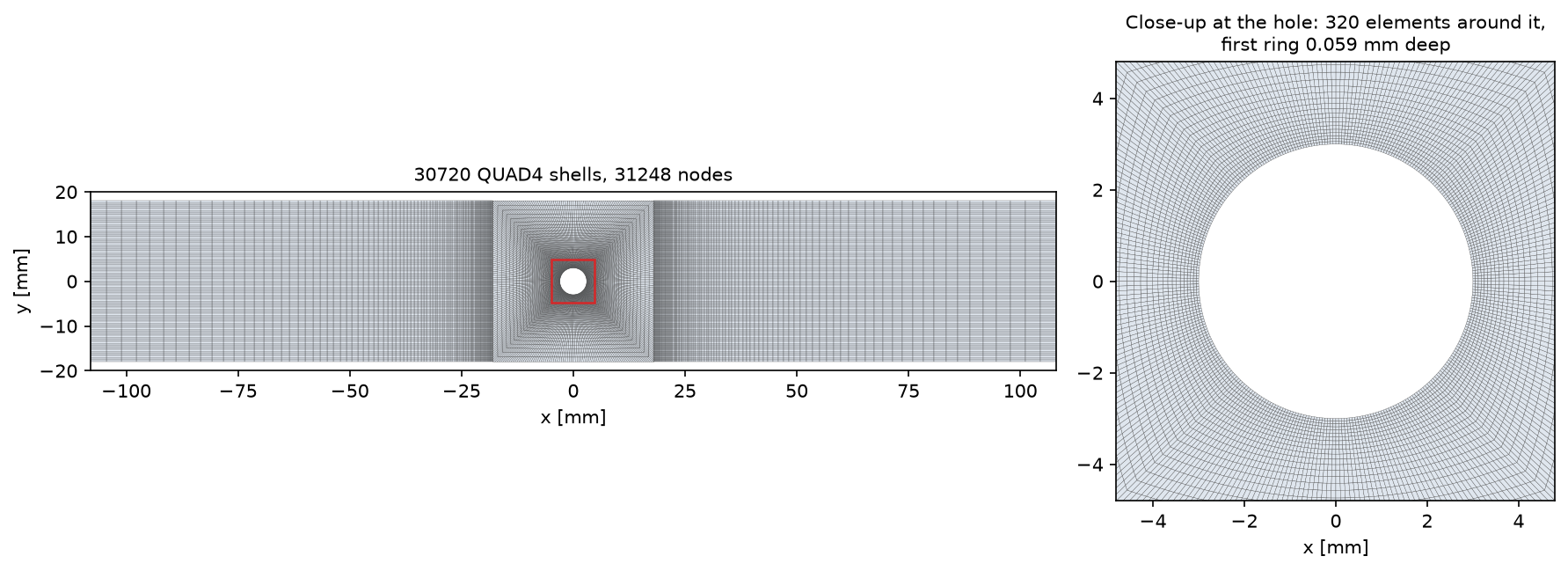
FIGURE 2. Finite element mesh of the specimen, $D = 6\,\mathrm{mm}$: 30720 QUAD4 shell elements and 31248 nodes; close-up at the hole.
RESULTS
The force carried by the net section, $\int \sigma_x h \,\mathrm{d}y$, equals the applied force within $0.02\%$ for every lay-up and plate, so the model is in equilibrium.
Laminate stiffness and ply stresses far from the hole
Far from the hole ($2W$ from its centre), the strain along the load is within $0.01\%$ of CLT for the quasi-isotropic and $\pm 45°$-dominated laminates, and $0.23\%$ below it for the $0°$-dominated one, where the disturbance of the hole extends further along the stiff fibres. Poisson's ratios are $0.310$, $0.311$ and $0.516$ (CLT: $0.312$, $0.311$, $0.516$). The ply stresses computed by Code_aster in this region match CLT within $0.05\%$ for the last two laminates, and within $1\%$ for the $0°$-dominated one, for the same reason. In the quasi-isotropic laminate under $\sigma_\infty = 100\,\mathrm{MPa}$, for example, the stress along the fibres is $265.8\,\mathrm{MPa}$ in the $0°$ plies, $93.6\,\mathrm{MPa}$ in the $\pm 45°$ plies and $-78.6\,\mathrm{MPa}$ in the $90°$ plies, with $12.7\,\mathrm{MPa}$ of transverse tension in the latter.
Stress concentration
Figure 3 shows the laminate stress $\sigma_x$ around the hole in the three specimens with $D = 6\,\mathrm{mm}$. In the $0°$-dominated laminate, the stress concentrates in a narrow band at the top and bottom of the hole and peaks at $4.38\,\sigma_\infty$. In the $\pm 45°$-dominated laminate, it spreads over a wider region and peaks at $2.62\,\sigma_\infty$.
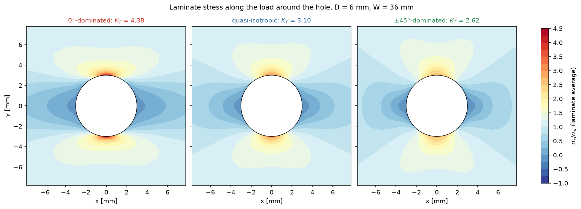
FIGURE 3. Laminate stress $\sigma_x / \sigma_\infty$ around the hole, $D = 6\,\mathrm{mm}$, $W = 36\,\mathrm{mm}$.
Figure 4 compares the stress along the hole edge with Lekhnitskii's solution. On the wide plate ($W = 20D$), the FEA follows the theory around the whole edge, within $0.08$, $0.25$ and $0.34\%$ of the peak for the three lay-ups, including the compressive stress at $\theta = 0$ ($-0.578$ against $-0.575$ for the $0°$-dominated laminate, $-1.006$ against $-1.000$ for the other two). The $\pm 45°$-dominated laminate has its highest stress not on the net section but at $\theta \approx 72°$: $2.563\,\sigma_\infty$ against $2.522$ at $90°$ (theory: $2.555$ at $71.8°$). The narrower specimen ($W = 6D$, dashed) raises the stress by $2$ to $4\%$.
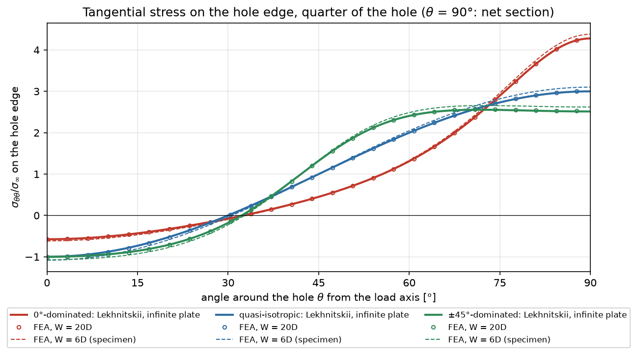
FIGURE 4. Tangential stress on the hole edge over a quarter of the hole, FEA against Lekhnitskii's solution for an infinite plate.
| $K_T$ (gross) | $0°$-dominated | Quasi-isotropic | $\pm 45°$-dominated |
|---|---|---|---|
| Lekhnitskii, infinite plate | $4.278$ | $3.000$ | $2.514$ |
| $W = 20D$: theory (with Tan) | $4.290$ | $3.008$ | $2.520$ |
| $W = 20D$: FEA | $4.282$ ($-0.18\%$) | $3.008$ ($-0.01\%$) | $2.522$ ($+0.08\%$) |
| $W = 6D$: theory (with Tan) | $4.414$ | $3.094$ | $2.593$ |
| $W = 6D$: FEA, $D = 3$ and $6\,\mathrm{mm}$ | $4.382$ ($-0.72\%$) | $3.102$ ($+0.25\%$) | $2.621$ ($+1.08\%$) |
The FEA gives the same $K_T$ for both hole sizes, to four digits, as expected from a linear model of two geometrically similar plates. On the specimens, the FEA differs from Lekhnitskii with Tan's correction by $-0.7$ to $+1.1\%$. Tan's correction is derived from an approximate stress distribution across the net section, and this is its accuracy at $D/W = 1/6$.
Stress along the net section
Figure 5 shows how the stress decays along the net section, away from the hole. On the wide plate, the FEA follows the approximation of equation (4) for the infinite plate. The highest stress concentration decays fastest: at $0.5\,\mathrm{mm}$ from the edge, the three curves cross, and at $d_0 = 1\,\mathrm{mm}$, the $0°$-dominated laminate is the least loaded, at $1.72\,\sigma_\infty$ against $1.81$ and $1.89\,\sigma_\infty$ on the specimens with $D = 6\,\mathrm{mm}$. This is why the point stress criterion is much kinder to the $0°$-dominated laminate than the peak stress is.
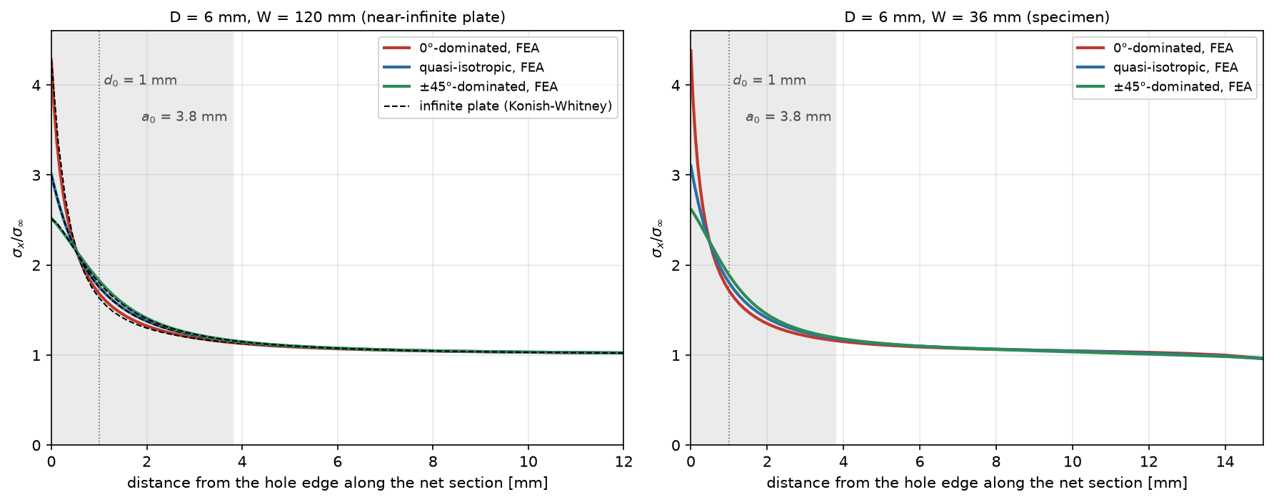
FIGURE 5. Stress $\sigma_x / \sigma_\infty$ along the net section, from the hole edge. Left: wide plate, FEA against the infinite-plate approximation. Right: specimen. Dotted: $d_0$; shaded: $a_0$.
Ply-by-ply failure at the hole
Figure 6 maps the Tsai-Wu failure index of each ply of the quasi-isotropic laminate at $\sigma_\infty = 100\,\mathrm{MPa}$. The $90°$ plies are the most loaded, at $0.79$ on the net section. These plies are loaded across their fibres, and the stress concentration adds to their transverse tension. They crack first, at $127\,\mathrm{MPa}$. The $\pm 45°$ plies reach $0.55$ at $72°$ around the hole, mostly in transverse tension and shear, and the $0°$ plies, which carry most of the load along their fibres, only $0.35$.
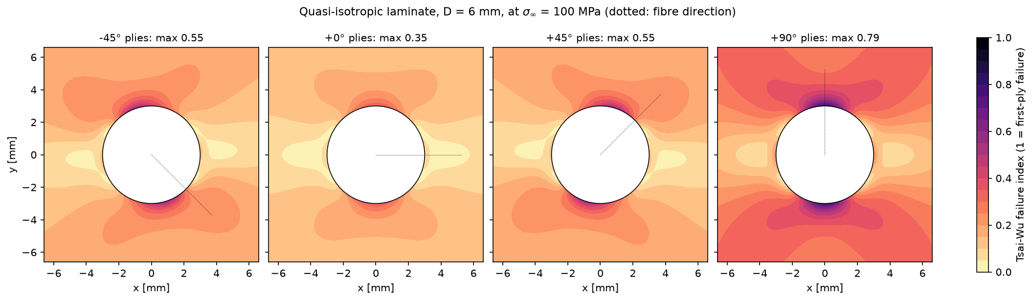
FIGURE 6. Tsai-Wu failure index (inverse of the load factor to first-ply failure) per ply orientation, quasi-isotropic laminate, $D = 6\,\mathrm{mm}$, $\sigma_\infty = 100\,\mathrm{MPa}$. Dotted: fibre direction.
At the hole edge, the first ply fails at a gross stress of $160\,\mathrm{MPa}$ in the $0°$-dominated laminate ($+45°$ plies, at $74°$ around the hole), $127\,\mathrm{MPa}$ in the quasi-isotropic one and $96\,\mathrm{MPa}$ in the $\pm 45°$-dominated one ($90°$ plies, on the net section). Hashin's matrix criterion gives $204$, $158$ and $141\,\mathrm{MPa}$. In every laminate, fibre failure starts in a $0°$ ply on the net section.
Notched strength of the three lay-ups
Figure 7 and the table below give the strengths, as the gross stress at fibre failure.
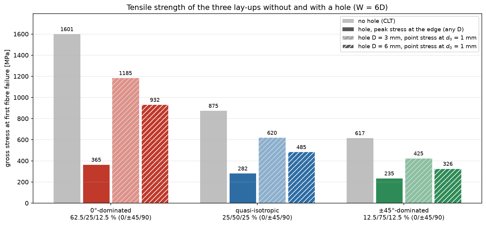
FIGURE 7. Tensile strength of the three lay-ups (gross stress at first fibre failure, $\mathrm{MPa}$): unnotched (CLT), and with a hole by the peak stress at its edge and by the point stress criterion, $W = 6D$.
| Strength ($\mathrm{MPa}$) | $0°$-dominated | Quasi-isotropic | $\pm 45°$-dominated |
|---|---|---|---|
| Unnotched, first-ply failure (Tsai-Wu) | $720$ | $394$ | $253$ |
| Unnotched, fibre failure $\sigma_0$ | $1601$ | $875$ | $617$ |
| Hole, first-ply failure at the edge | $160$ | $127$ | $96$ |
| Hole, fibre failure at the edge (peak stress) | $365$ | $282$ | $235$ |
| $D = 6\,\mathrm{mm}$, PSC (closed form) | $932$ ($949$) | $485$ ($483$) | $326$ ($332$) |
| $D = 6\,\mathrm{mm}$, ASC (closed form) | $983$ ($977$) | $538$ ($537$) | $377$ ($379$) |
| $D = 3\,\mathrm{mm}$, PSC (closed form) | $1185$ ($1193$) | $620$ ($617$) | $425$ ($427$) |
| $D = 3\,\mathrm{mm}$, ASC (closed form) | $1173$ ($1162$) | $639$ ($636$) | $448$ ($448$) |
The PSC and ASC strengths computed from the FEA stress profiles of the specimens are within $1.8\%$ of the closed forms (infinite plate with Tan's correction), which checks both.
Lay-up. Without a hole, the $0°$-dominated laminate is $1.83$ times as strong as the quasi-isotropic one and the $\pm 45°$-dominated laminate $0.71$ times. With a hole, the ranking stays the same, but the margins depend on the method:
| Ratio to quasi-isotropic | $0°$-dominated | $\pm 45°$-dominated |
|---|---|---|
| Unnotched | $1.83$ | $0.71$ |
| Hole, peak stress | $1.30$ | $0.83$ |
| Hole $D = 6\,\mathrm{mm}$, PSC | $1.92$ | $0.67$ |
| Hole $D = 6\,\mathrm{mm}$, ASC | $1.83$ | $0.70$ |
With the peak stress, the $0°$-dominated laminate keeps only $23\%$ of its unnotched strength (against $32\%$ and $38\%$ for the other two), and loses most of its advantage. With the point or average stress criteria, which account for the fast decay of its stress concentration, it keeps $58$ to $61\%$, as much as the others ($53$ to $62\%$), and its full advantage.
Hole size. The peak stress gives the same strength for both holes. The point and average stress criteria predict that the $3\,\mathrm{mm}$ hole leaves $27$ to $30\%$ (PSC) and $19\%$ (ASC) more strength than the $6\,\mathrm{mm}$ one. Open-hole tests on carbon/epoxy laminates show this hole size effect, which the characteristic distances were introduced to capture [ref. 5].
CONCLUSION
The open-hole tension of three carbon/epoxy laminates was modelled in Code_aster with layered shells, and every step was checked against theory. The laminate stiffness and the ply stresses far from the hole match CLT within $1\%$. On a wide plate, the stress along the hole edge matches Lekhnitskii's exact solution within $0.34\%$ of its peak. On ASTM D5766 specimens, the stress concentration factors, $4.38$, $3.10$ and $2.62$, are within $1.1\%$ of Lekhnitskii's values with Tan's finite-width correction. The Whitney-Nuismer strengths computed from the FEA are within $1.8\%$ of the closed forms, and the mesh is converged.
The case shows why a laminate with holes needs more than a stress concentration factor. The peak stress at the hole edge, the usual first check, predicts that the hole leaves only $23$ to $38\%$ of the unnotched strength, the same for any hole size, and that the $0°$-dominated lay-up loses most of its advantage. The point stress criterion predicts $53$ to $58\%$ for a $6\,\mathrm{mm}$ hole, $69$ to $74\%$ for a $3\,\mathrm{mm}$ one, and a $0°$-dominated lay-up still $1.9$ times as strong as the quasi-isotropic one. The allowable thus changes by a factor of up to $2.6$ with the method for the $6\,\mathrm{mm}$ hole, and $3.2$ for the $3\,\mathrm{mm}$ one, and the margins between the lay-ups change with it. Matrix cracking starts well before either prediction, at $96$ to $160\,\mathrm{MPa}$. It relieves the stress concentration in a real laminate, which is why the laminate is stronger than the peak stress suggests.
The point and average stress criteria depend on characteristic distances that are fitted to open-hole tests. The classical values used here for all three lay-ups are a starting point: a design allowable needs distances measured on the actual material and lay-up family, from a few coupon tests. The same model then predicts the strength for other hole sizes, widths and lay-ups, at a fraction of the cost of a test campaign. It also applies to open-hole compression, to filled holes and bolted joints, and to cut-outs of other shapes.
REFERENCES
- ASTM D5766/D5766M, Standard Test Method for Open-Hole Tensile Strength of Polymer Matrix Composite Laminates.
- Code_aster, version 17.4.
- S. G. Lekhnitskii, Anisotropic Plates, Gordon and Breach, 1968.
- S. C. Tan, Stress Concentrations in Laminated Composites, Technomic, 1994.
- J. M. Whitney and R. J. Nuismer, "Stress fracture criteria for laminated composites containing stress concentrations", Journal of Composite Materials, 8, 1974, pp. 253-265.
- S. W. Tsai and E. M. Wu, "A general theory of strength for anisotropic materials", Journal of Composite Materials, 5, 1971, pp. 58-80.
- Z. Hashin, "Failure criteria for unidirectional fiber composites", Journal of Applied Mechanics, 47, 1980, pp. 329-334.
- H. J. Konish and J. M. Whitney, "Approximate stresses in an orthotropic plate containing a circular hole", Journal of Composite Materials, 9, 1975, pp. 157-166.